
Siemens S7comm (`:102`), Allen-Bradley EtherNet/IP (`:44818`), 4–20 mA / HART, RS-232 Serial & File Watch-Folder (`PI UFL`) Connectors
Document ID: REF-CONNECTOR-PLC-SERIAL-UFL-GXPHISTORIAN-2026
Protocols Covered: Siemens S7comm (RFC 1006 ISO-on-TCP :102), Rockwell Allen-Bradley EtherNet/IP (CIP :44818) & Legacy PCCC/DF1, 4–20 mA Analog Current Loops + HART 7 (Bell 202 FSK), RS-232 / RS-422 Serial ASCII (MT-SICS, SBI, ASTM E1394), and Universal File / SMB Watch-Folders (OSIsoft PI UFL Replacement)
Typical Biopharma Equipment: Fedegari / Getinge Steam Autoclaves, Sartorius Biostat® D-DCU & Sartoflow®, MilliporeSigma Mobius® & Cogent® Skids, Emerson Rosemount / Endress+Hauser Sanitary Transmitters, Mettler Toledo XPR / Sartorius Cubis® II Analytical Balances, Advanced Instruments OsmoTECH® Osmometers, and Sartocheck® / Palltronic® Filter Integrity Testers
1. Visual Architecture: PLC Protocols (S7comm & EtherNet/IP) and 4–20 mA / HART Loops
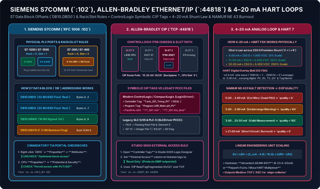
2. Deep Dive 1: Siemens S7comm Connector (RFC 1006 ISO-on-TCP Port 102)
European bioprocess skids—including Sartorius Biostat® STR / B-DCU / Sartoflow®, Fedegari & Getinge autoclaves, Syntegon / Bosch & Bausch+Ströbel filling lines, SKAN isolators, and GEA separators—are predominantly controlled by Siemens SIMATIC S7-1500, S7-1200, S7-300, or S7-400 PLCs.
While newer S7-1500 CPUs include an onboard OPC UA server, thousands of brownfield S7-300/400 skids (and high-speed S7-1500 skids without an OPC UA license) communicate via Siemens’ native S7comm (PUT/GET) protocol over TCP Port 102 (RFC 1006 ISO-on-TCP).
2.1 Physical Connector & How to Retrofit Older S7-300/400 PLCs Without Ethernet
- On Modern S7-1500 / S7-1200 PLCs:
- The CPU has two built-in RJ45 PROFINET ports: Port
X1(green PROFINET cable to internal skid I/O) and PortX2(Northbound Plant / Historian LAN). Plug a Cat6A Shielded cable into PortX2.
- The CPU has two built-in RJ45 PROFINET ports: Port
- On Legacy S7-300 / S7-400 PLCs (Only a 9-Pin
MPI / PROFIBUSDB9 Port):- If the S7-300 rack does not have a
CP 343-1Ethernet card, snap a Helmholz NETLink® PRO Compact (or IBH Link S7++) RJ45-to-MPI/PROFIBUS adapter directly onto the 9-pin femaleX1 MPI/DPport on the front of the CPU. - The adapter draws power directly from Pin 7 of the PLC’s MPI port, preserves a pass-through 9-pin socket on its back so the local skid HMI touchscreen stays plugged in, and exposes standard S7comm over Ethernet (
TCP Port 102)!
- If the S7-300 rack does not have a
2.2 Crucial Siemens Rack & Slot Connection Rules
When establishing an ISO-on-TCP (Port 102) connection to a Siemens PLC, you must specify the CPU’s Rack and Slot numbers (which form the TSAP connection parameter):
| Siemens PLC Family | CPU Rack | CPU Slot | Why? |
|---|---|---|---|
| SIMATIC S7-300 | 0 | 2 | In an S7-300 rail, Slot 1 is always reserved for the Power Supply (PS 307), so the CPU is always in Slot 2! |
| SIMATIC S7-400 | 0 | 2 or 3 | Depends on whether a wide 2-slot or 1-slot power supply is installed in the rack. |
| SIMATIC S7-1200 & S7-1500 | 0 | 1 | S7-1200/1500 architecture always addresses the CPU at Rack 0, Slot 1. |
2.3 How Siemens Data Block (DB) Byte-Offset Addressing Works
Inside a Siemens PLC, process variables intended for SCADA/Historian collection are grouped into a global Data Block (e.g., DB10 or DB100). Every variable has a deterministic byte offset from the start of the Data Block:
DB10.DBD0(Data Block Double-Word at Byte 0): 4-byte (32-bit) IEEE-754 Floating-PointReal(occupies Bytes0, 1, 2, 3, Big-EndianABCD). NextRealstarts atDB10.DBD4.DB10.DBW8(Data Block Word at Byte 8): 2-byte (16-bit) signedIntor unsignedWord(occupies Bytes8, 9).DB10.DBX10.0(Data Block Bit at Byte 10, Bit 0): Single boolean flag (0or1, e.g.,Sterilization_Hold_Active). Up to 8 booleans (DBX10.0throughDBX10.7) pack into Byte10.
2.4 The Two Mandatory Checkboxes in Siemens TIA Portal (For S7-1200 / S7-1500)
If you are connecting to an S7-1200 or S7-1500 over S7comm (Port 102), ask your automation engineer to verify two settings in Siemens TIA Portal:
- Uncheck “Optimized block access” on the Historian Data Block (
Right-click DB10PropertiesAttributes☐ Optimized block access) so TIA Portal assigns fixed byte offsets (0.0, 4.0, 8.0). - Check “Permit access with PUT/GET communication from remote partner” under
CPU PropertiesProtection & SecurityConnection mechanisms.
3. Deep Dive 2: Allen-Bradley EtherNet/IP (CIP :44818) & Legacy PCCC/DF1 Connectors
North American bioprocess skids—including Cytiva Xcellerex™ (PlantPAx® option), MilliporeSigma Mobius® & Cogent® TFF, Paul Mueller WFI skids, and SP Hull lyophilizers—use Rockwell Automation Allen-Bradley ControlLogix (1756-L7x / L8x) or CompactLogix (5069-L3x) PLCs communicating over EtherNet/IP (Common Industrial Protocol, TCP Port 44818).
3.1 Physical Connection & CIP Backplane Routing Path
- On CompactLogix (
5069/1769): Dual built-in RJ45 ports on the bottom/front of the processor. Plug your Cat6A cable into Port 2 (Configured in Dual-IP mode for Plant/Historian LAN). - On ControlLogix (
1756Modular Chassis):- A ControlLogix chassis has numbered vertical slots (
Slot 0, Slot 1, Slot 2, ...). - Often the
L83ECPU is inSlot 0, the internal skid I/O1756-EN2Tcard is inSlot 1, and the Plant / Historian1756-EN2TEthernet card is inSlot 2. - When connecting with Python
pycomm3(LogixDriver), the CIP route path10.20.60.15automatically routes across the ControlLogix backplane toSlot 0(or you can specify"10.20.60.15/1/4"if the CPU resides inSlot 4).
- A ControlLogix chassis has numbered vertical slots (
3.2 Symbolic Controller Tags (LogixDriver) vs. Legacy File Addressing (SLCDriver)
- Modern ControlLogix / CompactLogix: No memory register numbers needed! You query the exact symbolic tag name created in Studio 5000 Logix Designer:
- Controller-scoped tag:
"BR201_TT_01.Val" - Program-scoped tag:
"Program:MainProgram.Vessel_Weight_kg" - Quality Mapping from Rockwell PlantPAx® Add-On Instructions (AOIs): Every PlantPAx process object (
P_AIn) exposes both.Val(the float PV) and status bits.Sts_Bad(1 = Sensor Fault) and.Sts_Uncertain(1 = Simulated / Hand Override).GxPHistorianreads the entire structure in one CIP call and maps.Sts_Bad == 1quality = 0and.Sts_Uncertain == 1quality = 64!
- Controller-scoped tag:
- Legacy Allen-Bradley SLC 5/05 & PLC-5 (
PCCCover Ethernet or DF1 Serial):- Uses typed Data Files:
F8:0(Floating-Point File 8, Element 0),N7:10(16-bit Integer File 7, Element 10), andB3:0/1(Bit File 3).
- Uses typed Data Files:
4. Deep Dive 3: 4–20 mA Analog Current Loops, PT100 RTDs & HART 7 Connectors
4.1 Why Biopharma Still Uses 4–20 mA Current Loops instead of 0–10 V Voltage Signals
- Zero Voltage Drop Over Long Cables: By Kirchhoff’s Current Law, the current flowing into a series loop is identical at every point along a cleanroom cable run, regardless of wire resistance!
- Live-Zero Broken-Wire Detection (
4.00 mA= 0%,0.00 mA= Dead/Cut Wire):- If a sensor reads , you cannot tell whether the tank pressure is genuinely or someone severed the cable with a scissor lift.
- In a loop, of engineering range is and of range is :
- Under the international NAMUR NE 43 standard enforced by
GxPHistorian:I <= 3.60 mA(Downscale Burnout / Cut Wire): Mapped toquality = 0(Bad).3.60 mA < I < 3.80 mA(Underrange): Mapped toquality = 64(Uncertain).3.80 mA <= I <= 20.50 mA(Normal Operating Span): Mapped toquality = 192(Good).I >= 21.00 mA(Upscale Burnout / Short Circuit): Mapped toquality = 0(Bad).
4.2 How HART (Highway Addressable Remote Transducer) Works on Top of 4–20 mA
Smart sanitary transmitters (Endress+Hauser Liquiline / Cerabar, Emerson Rosemount 3051S, Micro Motion Coriolis flowmeters) superimpose a tiny Bell 202 Frequency Shift Keying (FSK) digital sine wave (1200 Hz = Binary 1, 2200 Hz = Binary 0) on top of the analog DC current.
- Because the high-frequency sine wave averages to exactly
0.000 mAover time, the analog PLC input card doesn’t even notice it—while a HART-to-Modbus-TCP Multiplexer (Pepperl+Fuchs KFD2-HMM-16 or Spectrum Controls) extracts up to 4 digital process variables per single pair of wires:PV(Primary Variable): Mass Flow Rate (kg/h)SV(Secondary Variable): Fluid Density (g/cm³)TV(Tertiary Variable): Fluid Temperature (°C)QV(Quaternary Variable): Totalized Mass (kg)
5. Visual Architecture: RS-232 Serial (DB9 / Moxa NPort) & File Watch-Folders (PI UFL)
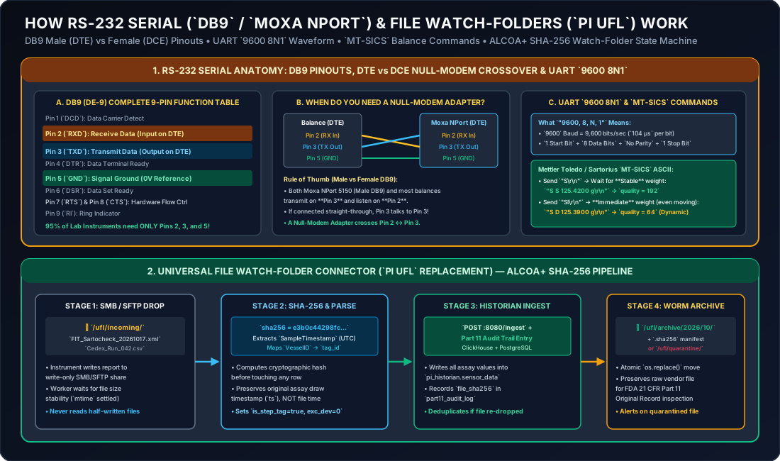
6. Deep Dive 4: RS-232 Serial (DB9), USB Virtual COM (FTDI) & Moxa NPort 5150
Standalone benchtop instruments in media prep, buffer kitchens, and QC labs (Mettler Toledo XPR / XSR / SevenExcellence, Sartorius Cubis® II, Advanced Instruments OsmoTECH®, Planer Kryo 560) output ASCII text strings over RS-232 Serial.
6.1 Complete 9-Pin DB9 (DE-9) Pinout Reference Table
| DB9 Pin | Signal Name | Direction on DTE (Male Plug / PC / Balance) | Direction on DCE (Female Socket / Modem) | Do You Need It for GxPHistorian? |
|---|---|---|---|---|
| Pin 1 | DCD (Data Carrier Detect) | Input | Output | Optional |
| Pin 2 | RXD (Receive Data) | Input (Listens) | Output (Transmits) | YES — Core Data Wire |
| Pin 3 | TXD (Transmit Data) | Output (Transmits) | Input (Listens) | YES — Core Data Wire |
| Pin 4 | DTR (Data Terminal Ready) | Output | Input | Only if hardware handshaking enabled |
| Pin 5 | GND (Signal Ground) | 0V Common Reference | 0V Common Reference | YES — Mandatory Common Ground |
| Pin 6 | DSR (Data Set Ready) | Input | Output | Only if hardware handshaking enabled |
| Pin 7 | RTS (Request To Send) | Output | Input | Tied to Pin 8 if RTS/CTS enabled |
| Pin 8 | CTS (Clear To Send) | Input | Output | Tied to Pin 7 if RTS/CTS enabled |
| Pin 9 | RI (Ring Indicator) | Input | Output | Unused |
6.2 How to Know Immediately If You Need a Null-Modem Crossover Adapter
- In RS-232, DTE (Data Terminal Equipment) transmits on Pin 3 and listens on Pin 2.
- Both the Moxa NPort 5150 (which has a Male DB9 port) and most analytical balances are wired as DTE.
- If you connect two DTE devices with a straight-through cable, both devices shout into Pin 3 while nobody is talking on Pin 2!
- The Solution: Insert a
$5DB9 Null-Modem Adapter (which internally swaps Pin 2 Pin 3 and Pin 7 Pin 8). Look at the orangeTx/RxLED on the Moxa NPort 5150 when you pressPrinton the balance—if it flashes orange, your pinout is correct!
6.3 How MT-SICS (Mettler Toledo Standard Interface Command Set) Maps to GxP Quality
When GxPHistorian parses a Mettler Toledo or Sartorius balance line (S S 125.4200 g\r\n):
S S <weight> <unit>(Stableweight): Balance vibration detector confirmed mechanical stability before printingquality = 192(Good).S D <weight> <unit>(Dynamic / Non-Stableweight): Weight was captured while the pan was still settling or driftingquality = 64(Uncertain).S +(Overload) orS -(Underload / Pan Removed): Hardware out-of-range errorquality = 0(Bad).
7. Deep Dive 5: Universal File Watch-Folder Connector (OSIsoft PI UFL Replacement)
For file-exporting GMP instruments—such as Sartorius Sartocheck® 4/5 Plus & Palltronic® Flowstar V filter integrity testers, Roche Cedex® Bio HT metabolite analyzers, Cytiva Sepax™ C-Pro cell processors, and C Technologies SoloVPE variable-pathlength spectrophotometers—GxPHistorian provides an ALCOA+ SHA-256 Watch-Folder Pipeline replacing the proprietary OSIsoft PI Interface for Universal File and Stream Loading (PI UFL):
- Write-Only SMB/SFTP Drop (
incoming/): The instrument is configured to auto-export its.csv,.xml, or.txtresult file to\\<historian-ip>\gxphistorian_ufl\incoming\<instrument_name>using a service account that has Create/Write permissions but zero Delete or Modify permissions. - File-Size Settling Guard: The Python watch-folder worker verifies that the file’s byte size and modification time (
mtime) have stabilized for (and no.tmp/.partlock file exists) so a large XML report is never parsed mid-transfer. - Cryptographic
SHA-256Original Record Seal: Before parsing a single line, the worker computes theSHA-256digest of the raw vendor file bytes and writes a.sha256manifest. - True Assay Timestamp &
LOCFStep Tag Ingestion: Extracts the instrument’s internalSampleTimestamp(UTC ms),BatchID/VesselID, and analytical parameters, posting them tohttp://edge-collector:8080/ingestwithis_step_tag = true(LOCF) andexc_dev = 0.0. - Immutable WORM Archive (
archive/YYYY/MM/): Atomically moves both the original vendor file and its.sha256seal into the date-partitioned archive directory (or intoquarantine/with an immediate operator alert if a schema error is detected).